
Main / GroupThreeLinkImp
Report on the implementation of the ICTP - S.Giusto wireless link as designed and evaluated in report #5.
Summary of the day:
Two teams were assembled, a "home" team assigned to the ICTP radio station and a "remote" team that travelled to where the client unit was going to be setup (S.Guisto).
The remote team assembled in the morning, did a general check on the equipment (without a proper checklist, this should be addresses beforehand) and traveled to S. Giusto (45.6475N, 13.7725E), approximately 8Km. away from the ICTP building.
The home team took position at the ICTP building (45.70417N, 13.72028E) and setup a signal generator to send a 2.400GHz signal towards the S.Giusto site. The purpose of this was to allow the remote team to align their antennas with the antenna at the ICTP site.
The remote team performed a site survey using the available spectrum analyzers [enter models here], scanning the 2.390GHz-2.410GHz range. The signal from the ICTP was being received with an omni antenna, with -80dB attenuation.
After this initial measurement, the remote team repeated the tests with a "cantenna" and a 24dBi parabolic antenna mounted on a mobile mast.
The levels detected with both the "cantenna" and the parabolic antenna were very similar, both close to -70dB. Since both antennas have a different gain (24dBi for the parabolic and 14dBi for the "cantenna") it is possible that the parabolic antenna was not correctly aligned with the ICTP antenna. The mount type, lacking a precision system to adjust azimuth and elevation, made its adjustment very difficult.
A scan along the 802.11b frequency range showed many signal in channels 1, 6 and 11; with most of the energy in channel 11.
The home team replaced the signal generator connected to the ICTP antenna for an unmodified WRT54G-L unit for the remote team to attempt a 802.11 connection to it.
Using the parabolic antenna, the team connected a Linksys WRT54G-L unit with a modified image to act as a client to the ICTP AP unit.
The initial tests were done using channel 6. A connection was established with the AP unit located in the ICTP building, but due to the amount of lost packets it was requested to the home team to switch to channel 4.
After switching to channel 4 a link was established with enough available bandwidth to perform live video and audio streaming, both ways, between the S.Giusto and the ICTP sites.
Network Diagram 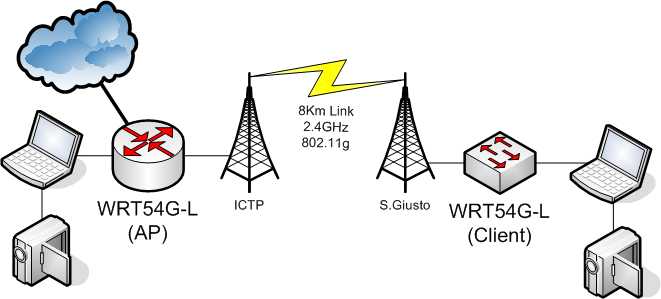
Equipment Specifications
ICTP Site:
- Transmit Unit: Linksys WRT54GL
- Firmware:
- Software version:
- Transmit Power: 18dBm
- Receiver Sensibility:
- Antenna Gain: 27.4dBi (n=0.7)
- Frequency Range: 802.11, Channel 6,4
S.Giusto Site:
- Transmit Unit: Linksys WRT54GL
- Firmware:
- Software version:
- Transmit Power: 18dBm
- Receiver Sensibility:
- Antenna Gain: 14dBi ("Cantenna") and 24dBi (parabolic)
- Frequency Range: 802.11, Channel 6,4