
Main / GroupTwoMuggia
11km Wireless Link to a Remote Site
Scenario
A repeater station needs to be set up 11km from a base station. There is no power grid in the remote location.
Link Feasibility & Link Power Budget Calculation
A low power radio system should provide wireless connectivity to remote users. Two WRT 54 GL Linksys boxes will be employed: the first one connects as a client to the Galileo Guest House AP and the second one is used as a local AP to users to connect to with their notebooks. Thus the station is basically a repeater. Special care should be taken to set the frequency channels of both boxes so that interference can be avoided.
The following pictures show the 11 km link connectivity details as predicted using Radio Mobile.
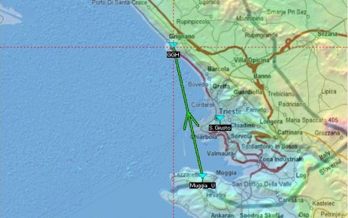
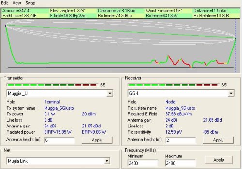
Due to the open Freznel Zone the antenna height is not too important.
Power Considerations
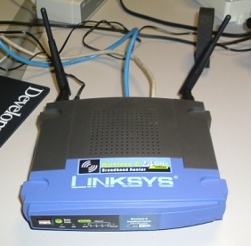
We chose the Linksys WRT 54 GL over the Metrix (Soekris Netboard and Atheros Mini PCI radio) due to the former's lower power consumption. One will be set up as a client and one as an access point which can optionally be turned on to give access for more than 4 (wired) connections.
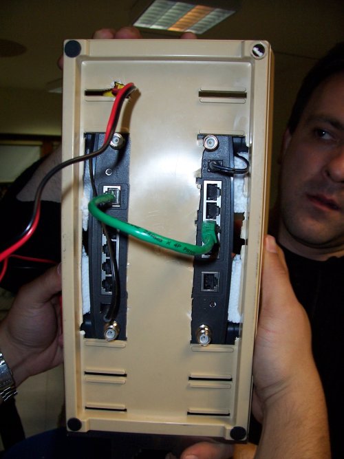
For the purposes of this site it may be best to remove the two boards from the Linksys enclosures and to put them in a weatherproof box with the battery and battery charger.
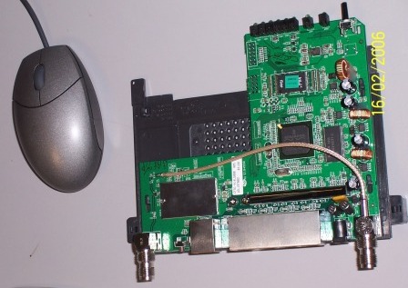
The WRT 54 GL (in a nutshell above) runs on 12V, but 6-18V is sufficient, due to a switch regulator on board. It uses 250mA at 12V, which is roughly 3W. A 5W solar panel can run the client or charge a lead acid battery via a battery charger when sunlight is not available. A fully charged 12V-7Ah battery can feed both the client and AP for approximately half a day non stop.
The Uni-solar solar panel at 1KW/m^2 gives 5W or say 0.3A at a maximum of 16.5V. A battery charger from ICPGlobal and a 12 V 7 AH Lead Acid Battery will be used.
Smart Battery Monitor
A device to power off the Linksys client when not in use will be very convenient. It will also help protect the battery from excessive discharge below critical voltage values.
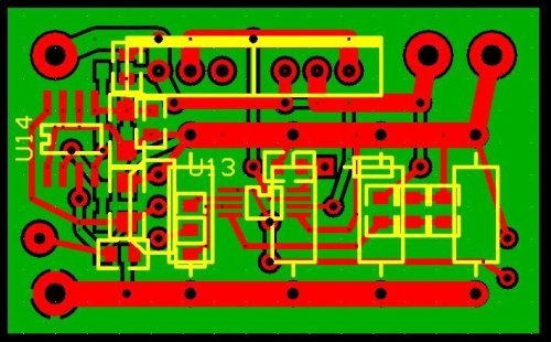
The following pictures shows an example of how this can be implemented. In this case two chips from Maxim have ben used: DS2438 and MAX1614. Component values should be calculated depending on the application. Check the links above for datasheets with details. The PCB is provided as a reference only.
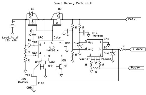
In this circuit the battery switch (max1614) disconnects the load, in this case the linksys boxes, when the voltage drops below 10.5V. The push buttom can be used to turn it back again. Instead the circuit can be modified so that the system turns back on again automatically after the batery is recharged.
On the other hand, the smart batery monitor (ds2438) is intended to have full control of the state of the batery. Charge level, remaining time of operation estimation, etc. In order to use this last feature a serial port with a 1-Wire interface is required. Some code running on the embedded system is necesary as well to implement monitoring. Maxim provide SDK and API which is free of charge when you buy the components.
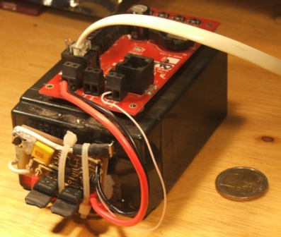
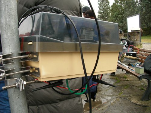
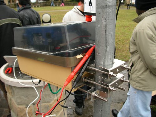
The photo below shows an implementation of the battery pack used for an "in field ants measuring system" by the complexperiments team.
Assembly
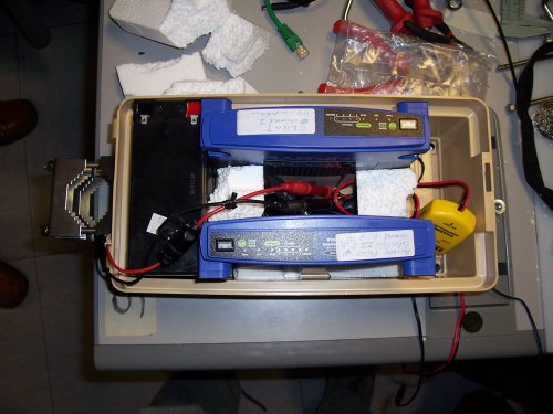
Our actual access point does not have a smart battery pack due to a lack of parts. An improvised "waterproof" container was used. In fact we just cut holes in the bottom, which was sufficient for this competition.
Financial Planning
| Part | Cost |
|---|---|
| Linksys (2 x 60 EUR) | 120 EUR |
| Weatherproof Casing | 10 EUR |
| Solar Panel & Battery Charger | 60 EUR |
| Lead Acid Battery | 20 EUR |
| Antenna | 90 EUR |
| Various parts | 10 EUR |
| Installation | Voluneer effort |
| Total | 310 EUR |
Further budget reductions can be achieved by using a Cantenna and a TV satellite dish for the directional antenna (30 EUR in parts instead of 90). On the other hand, at soem extra cost an omni-directional antenna can be added to the access point at the remote site for wider coverage there.
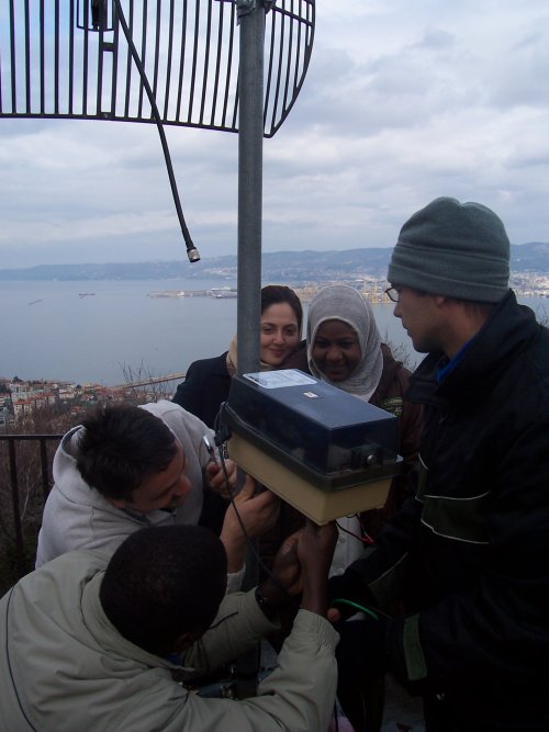
Local Test
A complete simulation will be carried out at very short distance from the base station. I.e. assemble and test all equipment and set up link. A check list for the actual deployment is compiled at this time. The GGH side of the link with Carlo tinkering is shown below.
Site Access
Carlo secured permission to use the Muggia site, and will accompany us on the day. The site has previously been visited by him. We will check the weather forecast in the days before deployment. One should also check on events in Trieste which may hinder access to the site or cause excessive traffic.
Deployment
Checklist of items and spares, extra connectors where possible, without overloading yourself
- Compass, GPS, map, ruler
* Information: Azimuth=347.4 deg, antenna height at Muggio=5m, and elevation angle=0.226 deg
* Battery, solar panel, battery charger
* Inverter, voltage meter
* Access points in weatherproof enclosure
* A portable Spectrum Analyzer (or two)
* Antenna and RF cables and connectors, crimpers
* Mast and accessories
* Tools: pliers, wrenches, screwdrivers, tape measure, etc.
* Laptops with proper software, fully charged
* Ethernet cables & network tester
* Gloves, protective & rain gear
* Communication with base (walkie talkies or cell phones)
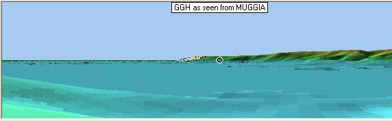
Results
GGH as seem from Muggia. It's a long 11km...
Due to the competition's time limits a proper site survey was not done -- we had to race the competition to get the structure up, and the spectrum analyzer was used afterwards for alignment.
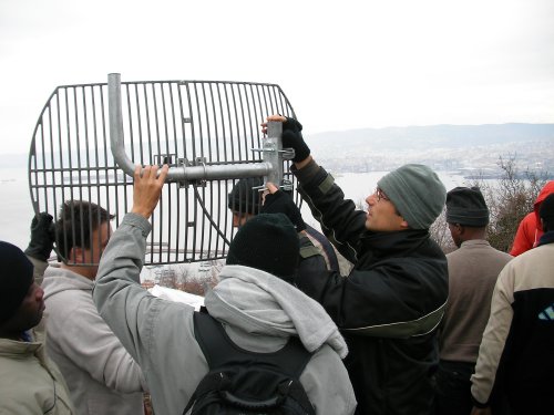
And the competition...
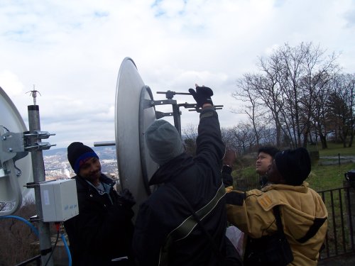
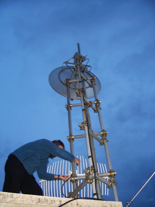
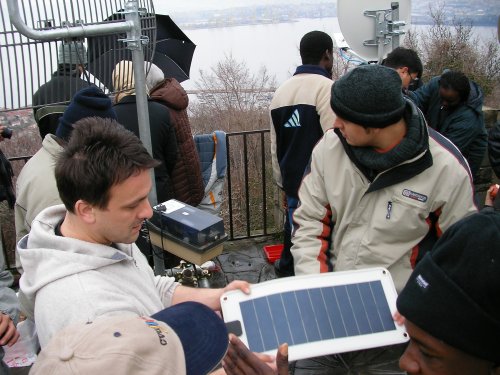
After assembling the tripod and mast the antenna and access point were attached.
The solar panel was attached, mostly for illustrative purposes, as the sun was nowhere to be seen, and Carlo warned of approaching rain.
Spectrum analyzers were used to read Carlo's signal from the signal generator.
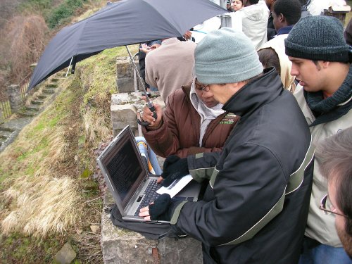
Meanwhile we connected to our system, protecting the laptop from rain. Good thing we planned for rain and brought an umbrella!
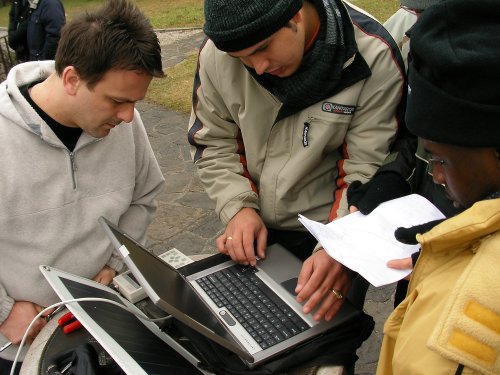
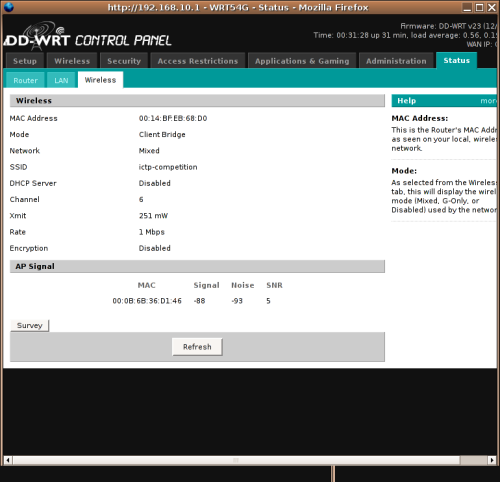
Then the access point at GGH was connected. Initially the SNR was 69:86. For some time part of the team refreshed the signal level on the client's web interface while others fine-tuned the antenna alignment.
This initial screenshot of the signal levels was uploaded over the 11km wireless link:
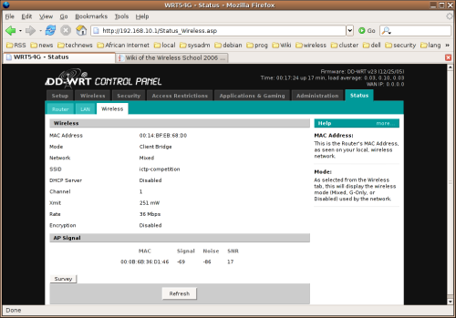
We switched to channel 6 due to interference on channel 1. A connection was made and dropped several times but with further vertical alignment we managed to establish a link strong enough to make a voice call to Venezuela, and the internet was surfed. The screenshot was taken at an SNR of 88:93 but a much better ration was actually achieved on channel 6.
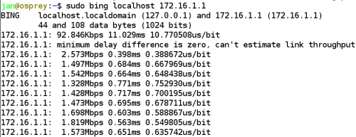
An estimated throughput (reported by bing) of 1.5Mbps was achieved by one laptop with two other users simultaneously using the link!
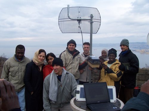
A happy but tired group poses for a photo before dissassembling.
Conclusion
Although the link was successful it was not stable enough to leave on as a permanent remote site.
We could have paid more attention to the following points:
- Set tripod more level (we had assembled it for height rather than stability)
- Alignment was difficult and a slow, methodical approach with more fine-grained controls would have been advantageous.
- Note the EM field was not aligned with physical structure of the antenna, probably due to its age and condition. One wants to make sure that the major lobe is used -- a link budget calculation before hand gives an indication of the expected values.
- First align horizontally, then vertically (Our antenna is more sensitive to horizontal adjustment -- it is better to leave the fine-grained adjustment for last).
- Test each position thoroughly, for a few minutes, with no adjustments on either side. Change one side at a time.
- First test with the signal and noise level readings, then ping, then route to internet, taking one step at a time.
- Though we knew Carlo's antenna was vertically aligned, we never explicitely checked this on the day.
- Keep all IP addresses, routes, DNS, etc. clearly written down with you. Everyone forgets something amidst all the detail.