Tuesday13 Group3
From School2007
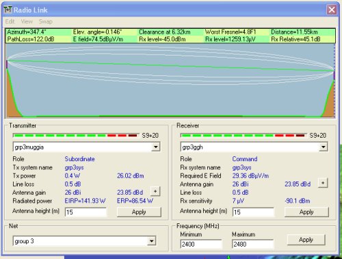
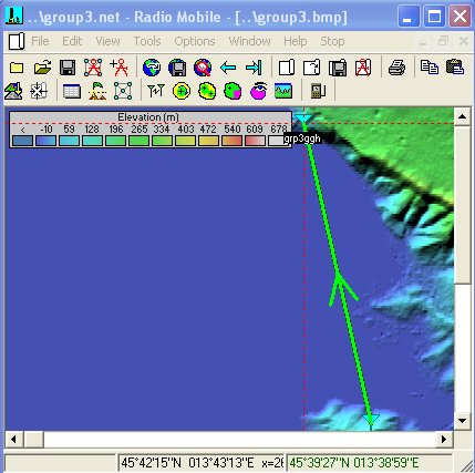
[edit] Link Budget Simulation
Today wiki is a broken one! :-)
More seriously, the link budget calculation was a very treaty work to do because of the amount off map data components that were supposed to be downloaded from internet. But just watch this space, will get back with an updated diary. Keep on...
During the morning we had a review of the basic concepts required to undertand the radiopropagation process. First of all, we started with the scentials of electromagnetics like, electromagneic interaction, TEM mode, the relationship between the power and the Poynting vector, Doppler effect among others.
Since polarization is a key factor in radiocommunications we spent some time on it which was very useful for most of us. The propagation process is a complicated one but was clearly explained by Professor Strusak. The effect that enviromental conditions imposes over radio liks was analysed. Most of the time the effect is frequency dependend. So, care requirements are not the same for all kind of links. LOS propagaion model as well as the two ray propagation model was studied. We could see that the losses are higher in a two rays propagation model and it is even worse if a fading channel is considered, which is closer to the real situation.
We could see that in order to have LOS conditions we not only need to guarranty the LOS itself but also the 1st Fresnel zone around it.
The second topic was presented by Marco Zennaro; he taught us how to compute the link budget in a radio link. We were introduced to the matric expressed in dB (Decibels), dBi and dBm. Basically the link budget is obtained by adding (with sign) all the gains and losses of the radio link. As gains we have to considere: the transmitter power, the Tx antenna gain and the Rx antenna gain; on the other hand we have to considere the next loses: Conector losses at Tx side, cable losses at Tx side, propagation losses, cable losses at Rx side and conector losses at Rx side. Addittionally, what usually peoplo does is to consider a margin of power as extra losses, this is not only for the propagation fading but alo because of the performance redction of all the hardware elemets involved in the link.
Total Gain = TX Power Radio 1 + Antenna Gain Radio 1 - Cable Losses Radio 1 + Antenna Gain Radio 2 - Cable Loses Radio 2
Before lunch we had a theoretical class about a simulation program (Radio Mobile) that can help to determine if a radio link will work in real life. This software makes use of DEM in order to compute the propagation conditions in a radio link.
After lunch we had the chance to put together all that we had learnt during the morning by making the simulation of a radio link in the Trieste area. We found it very useful and very interesting. We kept playing with it for a long time. Ultimately, we found how to select the pointing direction of antennas other than omni (e.g. Yagi-Uda). We shared our "findings" with Mr. Ermanno as well.
[edit] The following is a comment
By a guy from Kenya
Hellom Group 3:
The link budget you did was based on the assumption of free space loss i.e FSL: 32.44 + 20 log f/MHz + 20 log d/KM.
In reality this free space loss formula is not very accurate. it does not take into consideration; earth bulge, precipitation in the air, antenna heights, temperature;trees, buildings, water mass, terrain. it assumes two things:
- the air is free but we know it has O2, NOx, CO2 partyicles that cause dispersion and attenuation of the electromagnetic waves. - the earth is flat: not true we know it is rough and is like a ball, an earth bulge factor k= 3/4 is to be considered.
there are other better propagation prediction models e.g:
okumara Hata model, lees model, Egli model, weibefrger ,model and I am working on a radio path analysis model here at kenyatta university in Kenya.
Have a great day and see you soon.


