Link Budget calculation
Marco Zennaro
Definition
Link budget calculation=determining if a link is feasible or not, given:
- the characteristics of the radios
- the characteristics of the antennas
- the distance between the radios
- the allowed power!
Characteristics of the radios
Transmit power: it is expressed in milliwatts or in dBm
Characteristics of the radios
Minimum Received Signal Level: it is the sensitivity of the receiver
- it is always expressed as a negative dBm (-dBm)
- it is the lowest power of signal the radio can distinguish
- the minimum RSL is dependent upon rate, and the lowest rate (1 Mbps) has the greatest sensitivity
- the minimum will be in the range of -75 to -95 dBm
- should be provided by the manifacturer
Characteristics of the antennas
Antennas are passive devices that create the effect of amplification by virtue of their physical shape
- antennas have the same characteristics when receiving and when transmitting
- a 12 dBi antenna is simply a 12 dBi antenna!
- omnidirectional antennas have a gain of 5-12 dBi
- sectorial antennas have a gain of 12-15 dBi
- parabolic antennas have a gain of 19-24 dBi
Characteristics of the antennas
Part of the signal's energy is lost in the cables, the connectors and other devices going from the radios to the antennas
- the loss depends on the type of cable used and on its length
- signal loss for short coaxial cables including connectors is quite low, in the range of 2-3 dB
- it is better to have cables as short as possible!
Path Loss
When calculating the path loss, several effects must be considered: free space loss, attenuation and
scattering.
Free space loss: the signal power is diminished by geometric spreading of the wavefront.
The further away the two radios, the smaller the received signal. This is independent from the environment,
depending only on the distance.
Using decibels to express the loss, and using 2.45 GHz as the signal frequency, the free space loss is:
Lfsl=40 + 20*log(r)
where Lfsl is expressed in dB and r is the distance in meters.
Path Loss
Attenuation takes place as some of the signal power is absorbed when the wave passes through solid objects
as trees, walls, windows, etc.
It is very difficult to quantify. The most convenient way is to express its contribution is by adding an "allowed
loss" to the free space loss. For example, experience shows that trees add 10 to 20 dB loss per tree
in the direct path.
Taking into account the attenuation, the path loss is then:
Lfsl=40 + 20*log(r) + L(allowed)
where Lfsl is expressed in dB and r is the distance in meters.
Path Loss
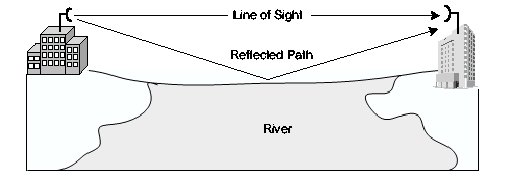
Scattering takes place as some of the RF energy reaches the receiving antenna
directly, while some bounces off the ground. Part of the RF energy which bounces off the ground reaches
the receiving antenna, but later than the direct signal.
This effect is called multipath, fading or signal distortion.
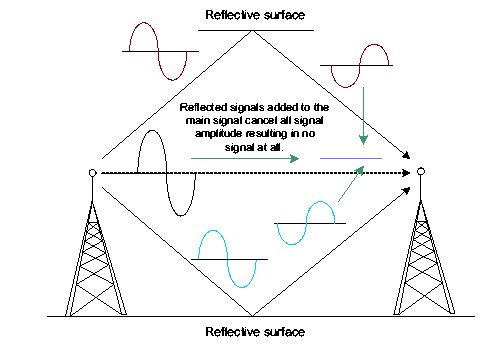
Path Loss
In some cases, the two signals add together, and cause no problem. When the two signals add together out of phase, the received signal is almost worthless: this is known as nulling.
Path Loss
A technique used to deal with multipath is antenna diversity:
it consists of adding a second antenna to the radio. Multipath is a very location-specific
phenomenon.
Antenna switching diversity: multiple antennas on multiple inputs, with one receiver. In transmission,
the last used antenna is used.
Path Loss
A simple way to take into account scattering in the calculation of the path loss, is
to change the exponent of the distance factor of the free space loss formula. The more the
scattering, the higher the exponent. For an outdoor environment with tress, an exponent of 3
can be used, while one of 4 for an indoor environment.
Taking into account scattering and attenuation, the path loss is then:
Lfsl=40 + 10*n*log(r) + L(allowed)
where Lfsl is expressed in dB and r is the distance in meters.
Path Loss
In practice, just the free space loss is calculated. The environment can bring further
signal loss, and should be considered for the exact evaluation of the link.
To evaluate if a link is feasible, one must know the characteristics of the
equipment being used, and evaluate the path loss.
If you are using two different radios, you should perform the calculation twice, once for
each direction!
Allowed Power
When performing a link budget calculation, we must take into account the power limits which
are imposed by the regulatory boards (FCC in the US).
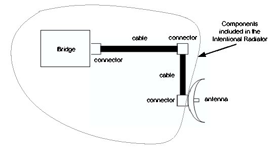
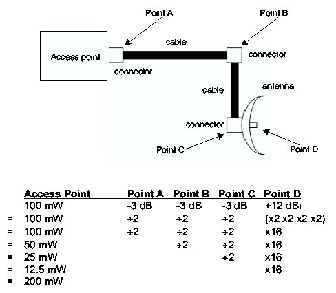
We define an intentional radiator as the RF
device and all cabling and connectors up to,
but not including, the antenna.
Allowed Power
Any reference to power output of the
Intentional Radiator refers to the power
output at the end of the last cable or
connector before the antenna.
If a 30 mW transmitter loses 15 mW of
power in the cables and another 5 mW from
the connectors, the power of the intentional
radiator is 10 mW (30-15-5=10).
Allowed Power
Allowed Power
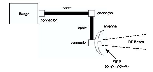
The EIRP is the Equivalent Isotropically
Radiated Power.
EIRP is the power actually radiated by the
antenna element and is important because
- it is regulated by the FCC or other regulatory agency
- it is used in calculating whether or not a wireless link is viable
Allowed Power
The EIRP takes into account the gain of the antenna.
The FCC has rules defining both the power
output at the intentional radiator and the
antenna element.
Allowed Power
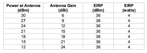
In the setup of a PtMP link, the FCC limits
the EIRP to 4 Watts.
The power limit set for the intentional
radiator is 1 Watt.
Allowed Power
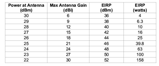
Ptp links include a single directional
transmitting antenna and a single directional
receiving antenna.
In the case of PtP links, the power of the
intentional radiator is still limited to 1 Watt,
but the limit of the EIRP increases with the
gain of the antenna
The FCC mandates that for every 3 dBi above
the initial 6 dBi of antenna gain, the power
at the intentional radiator must be reduced
by 1 dB from the initial +30 dBm
Allowed Power
Link Budget Calculation
If the powers used are within the limits imposed by the regulatory boards, then we can
perform the link calculation.
Adding up all the gains and subtracting all the losses gives:
TX Power Radio 1 +
Antenna Gain Radio 1 -
Cable Losses Radio 1 +
Antenna Gain Radio 2 -
Cable Loses Radio 2
-------------------------
Total Gain
Link Budget Calculation
Subtracting the Path Loss from the Total Gain:
Total Gain -
Path Loss
-------------------------
Signal Level at one side of the link
If the resulting signal level is greater than the minimum received signal level, then
the link is feasible!
On a given path, the variation of path loss over time can be large, so a certain link margin
should be considered. A margin of 10-15 dB is fine. To take into account attenuation and multipath, a margin of
20 dB should be safe enough.
Example of Link Budget Calculation
We want to estimate the feasibility of a 5 km link, with one AP and one client.
Access Point:
- Tx power= 100mW (20 dBm)
- Sensitivity= -89 dBm
- Antenna= Omni with 10 dBi gain
- Cables are short, with a loss of 2 dB
Example of Link Budget Calculation
Client:
- Tx power= 30mW (15 dBm)
- Sensitivity= -82 dBm
- Antenna= Sectorial with 14 dBi gain
- Cables are short, with a loss of 2 dB
Example of Link Budget Calculation
Adding up all the gains and subtracting all the losses gives:
20 dBm (TX Power AP) +
10 dBi (Antenna Gain AP) -
2 dB (Cable Losses AP) +
14 dBi (Antenna Gain Client) -
2 dB (Cable Loses Client)
-------------------------
40 dB (Total Gain)
Example of Link Budget Calculation
The path loss for a 5 km link, considering only the free space loss, is:
Path Loss= 40 + 20*log(5000) = 113 dB
Subtracting the path loss from the total gain gives:
40 dB - 113 dB = -73 dB
Since -73 is greater than -82 (receive sensitvity of the client), the signal level is
enough for the client to be able to hear the AP. There is only 9 dB of margin, which may not
be enough to protect against extreme weather conditions.
Example of Link Budget Calculation
Now we calculate the link from the Client back to the AP:
15 dBm (TX Power Client) +
14 dBi (Antenna Gain Client) -
2 dB (Cable Losses Client) +
10 dBi (Antenna Gain AP) -
2 dB (Cable Loses AP)
-------------------------
35 dB (Total Gain)
Example of Link Budget Calculation
The path loss is the same on the return trip.
The received signal on the AP is then:
35 dB - 113 dB = -78 dB
Since -78 is greater than -89 (receive sensitvity of the AP), the signal level is
enough for the AP to be able to hear the client. There is 11 dB of margin. Using a 24 dBi dish on the client side
rather than the 14 dBi antenna, would add an additional 10 dB of gain on both directions of the link.