Ethernet Basics: Thin Ethernet
The Basics
Thin Ethernet, officially called 10 Base-2, is a less expensive version
of 10 Base-5 (Thick Ethernet) technology.
It uses a lighter and thinner coaxial cable and dispenses with the external
transcievers used with 10 Base-5.
Topology & Distance Limits
10 Base-2 uses an RG-58A/U coaxial cable and is wired in a bus topology.
Each device on the network is connected to the bus through a BNC "T"
adapter, and each end of the bus must have a 50 Ohm terminator attached.
Each node on the bus must be a minimum of 0.5 meters (1.5 feet) apart, and
the overall length of the bus must be less than 185 meters (606 feet).
Figure One graphically illustrates a sample 10 Base-2 network.
NOTE: It is not possible to locate the node away from the BNC "T"
adapter by connecting a coaxial cable between the "T" and the node's
BNC connector. Doing so will detune the network, and will almost certainly
result in major problems.

Figure One
Sample 10 Base-2 Network
Advantages & Disadvantages
As with any networking technology, 10 Base-2 has advantages and disadvantages
inherent in its design. These attributes can make it very useful for a
particular network design or they may point the designer to another
technology. Some advantages and disadvantages are:
Advantages
- Conceptually Simple
- 10 Base-2 networks are simply daisy-chained together with coax cable
and "T" adapters. There are usually no hubs, transcievers, or
other devices used.
- Relatively Inexpensive
- Due to the simplicity inherent in the design of 10 Base-2, it can be
an inexpensive technology to implement.
- Noise Immunity
- The coaxial cable used in a 10 Base-2 network is very well shielded,
and has a very high immunity from electrical noise caused by outside sources.
Disadvantages
- Difficult To Change
- Reconfiguring a 10 Base-2 network is somewhat difficult to do once it
is in place. Any changes to the network will result in at least some
"down time," as the bus must be broken and a new section spliced
in at the point of the break.
- Fault Intolerant
- If any device or cable section attached to the network fails, it will
most likely make the entire network go down.
- Difficult Troubleshooting
- 10 Base-2 networks are very difficult to troubleshoot. There is no
easy way to determine what node or cable section is causing a problem, and
the network must be troubleshot by a "process of elimination."
This can be very time consuming.
- Specialized Cable
- The RG-58A/U coaxial cable used in 10 Base-2 networks can not be used
for any other purpose. In the event that the network is changed to another
type, then the cable will have to be replaced.
10 Base-2 technology is generally well suited to small networks which will
not change much after the initial installation is complete. It is not well
suited for larger networks or any setup which is expected to change over time.
One application where 10 Base-2 excels is as a "backbone" technology
for interconnecting multiple 10 Base-T
hubs. This allows the advantages of 10 Base-2's strengths to be utilized
while keeping the repeater count within limits.
Usually the hubs will not move once they are installed. A diagram of this
type of setup is shown in Figure Two.

Figure Two
10 Base-2 Backbone Application
The "Thinnet Tap" System
Above it was mentioned that 10 Base-2 devices are interconnected by
daisy-chaining them together. Although this is simple and easy to
accomplish, it results in a network which is very vulnerable to problems
caused by users damaging or disconnecting cables. These problems are
also very difficult to isolate. Therefore, a need was identified to provide
a way to make the system more robust. The result of this need is the
"Thinnet Tap" System.
The Thinnet Tap System is designed to allow the main network coaxial cable
to be located away from individual nodes, and also to allow connecting and
disconnecting devices "on the fly" without dropping the entire
network in the process.
The system consists of a specialized Tap Assembly which connects to the main
coaxial backbone cable, and Drop Cables which connect the individual devices
to the tap. Inside the tap is a microswitch which detects whether or not a
drop cable is plugged in to it. If no cable is attached, then the tap
simply behaves like a wire and passes the signal along the coaxial cable.
Figure Three shows a conceptual diagram of a Tap Assembly without a
drop cable connected to it.

Figure Three
Tap Assembly Without Drop Cable
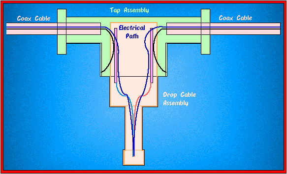
The Drop Cables are the key to making the system work. Inside each Drop
Cable are two coaxial cables and the equivilant of a BNC "T"
adapter. When a Drop Cable is connected to a Tap Assembly, it toggles
a microswitch in the tap. Each side of the Tap then electrically connects
to one of the coaxial cables in the Drop Cable, which "loops"
the signal to the node, then back to the other side of the Tap. This
results in an unbroken network which is electrically the same as
connecting with a traditional BNC "T" adapter, but in a
more convenient manner. Figure Four is a conceptual diagram
of a Tap Assembly mated with a Drop Cable.

Figure Four
Tap Assembly With Drop Cable
NOTE: Never attempt to lengthen a Drop Cable with a length of coaxial
cable and a BNC coupler. This is the same as locating a "T"
adapter away from the node, and will cause major network problems!