Ethernet Basics: 10 Base-T
Ethernet was originally designed to operate over a heavy coaxial cable, and
was later updated to also support a thinner, lighter, coaxial cable type.
Both systems provided a network with excellent performance, but they utilized
a bus topology which made changing a network a difficult proposition, and
also left much to be desired in regard to reliability. Also, many buildings
were already wired with twisted-pair wire which could support high speed
networks. Installing a coaxial-based Ethernet into these buildings would
mean they would have to be rewired. Therefore, a new network type known as
10 Base-T was introduced to increase reliability and allow the use of
existing twisted-pair cable.
Topology & Cabling
10 Base-T utilizes Category 3 (or higher) Unshielded Twisted Pair (UTP)
cable in a star topology. Each node on the network has its own cable run
back to a common hub, and each of these cable runs may be up to 100 meters
(330 feet) in length. Figure One shows a simple 10 Base-T network.
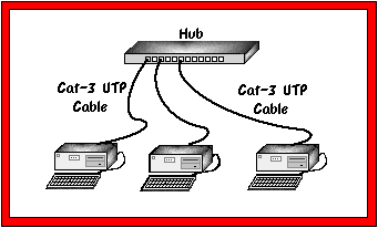
Figure One
10 Base-T network
10 Base-T can also be wired in a tree topology, where one "main"
hub is connected to other hubs, which are in turn connected to workstations.
Please note that the depth of a 10 Base-T tree network is limited to one
layer below the main hub. It is also possible to combine 10 Base-T with
any combination of the other 10 Mbps Ethernet technologies in an infinite
number of ways to meet nearly any requirement. Figure Two shows a
combination of 10 Base-T and 10 Base-2.
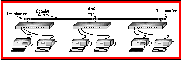
Figure Two
10 Base-T and Thin Ethernet Combination
Advantages & Disadvantages
10 Base-T has various advantages and disadvantages which make it suitable
for some applications and less suitable for others. Some of them are listed
below:
Advantages
- Fault Tolerant
- Since each node on a 10 Base-T network has its own cable connecting it
to a central hub, it is far less likely that any node can cause the entire
network to fail. The hub also has a "partitioning" function built
into it which allows it to detect a problem on any of its ports. If a
problem is found, the node is disconnected from the rest of the network.
This isolates the problem until the node can be troubleshot and repaired.
- Easy Troubleshooting
- Because of the partitioning function built in to the hubs and the
star-wired topology, it is generally easy to troubleshoot a 10 Base-T
network. In a worst-case scenerio, one can be troubleshot by simply
disconnecting nodes from the hub one at a time until the network recovers.
Usually, the hub will give an indication as to which node is causing a
problem, allowing the technician to troubleshoot that node as opposed to
spending many hours finding where the problem is.
- Easy Moves & Changes
- Disconnecting a node from the network has no effect whatsoever on the
rest of the network. Therefore, moving an attached device is simply a
matter of unplugging it from the hub and reconnecting it somewhere else.
- Uses UTP Cable
- Many buildings are already wired with UTP cable which can support a 10
Base-T network. Even in the event a building is not wired with UTP already,
it is still prefereable to install UTP than any other type of cable, as UTP
will support other applications later, whereas other cable types will
generally be specific to one network type. This allows leveraging the UTP
cable investment for other applications many years later.
Disadvantages
- Distance
- 10 Base-T only allows distances from the hub to the node of 100 meters (330 feet). In some installations, this can be a major problem if nodes need to be located farther away.
- Sensitive To Noise
- The nature of UTP cable makes it considerably more sensitive to electrical noise than coaxial cable. Generally, this rules 10 Base-T out as an option for installations on factory floor environments or other locations with a high ambient noise level.
Cabling Considerations
10 Base-T uses two pairs of wires: one pair for transmission and the
second pair for recieve. The physical connector used is an 8 position
modular plug, commonly referred to as an RJ-45. All cables must be rated
at a minimum of Category 3, and must be wired such that pins 1 & 2 are
on one twisted pair and pins 3 & 6 are on a second pair. Common wiring
standards which meet this requirement are EIA/TIA T568A and T568B.
There are two pinouts used: MDI for DTE devices (such as computers, printers,
etc.) and MDI-X (hubs). Connecting an MDI port to an MDI-X port requires a
straight through cable, and connecting either MDI to MDI or MDI-X to MDI-X
requires a crossover cable. Pinouts of the MDI and MDI-X interfaces are
shown in Table One.
| MDI PINOUT |
|---|
| Pin | Signal |
|---|
| 1 | T+ |
| 2 | T- |
| 3 | R+ |
| 6 | R- |
| MDI-X PINOUT |
|---|
| Pin | Signal |
|---|
| 1 | R+ |
| 2 | R- |
| 3 | T+ |
| 6 | T- |
Table One
10 Base-T Pinouts
There are several applications for crossover cables in 10 Base-T networks.
The most common reason is to cascade hubs together in a tree topology.
If both hubs have only MDI-X ports then a crossover cable is needed.
Another application for a crossover cable is to connect two DTE devices
together without a hub.
A standard 10 Base-T crossover cable wiring diagram is shown in
Table Two.
| 10 Base-T Crossover Cable |
|---|
| SIDE 1 | WIRE COLOR | SIDE 2 |
|---|
| 1 |
White/Orange |
3 |
| 2 |
Orange/White |
6 |
| 3 |
White/Blue |
1 |
| 6 | Blue/White | 2 |
Table Two
Crossover Cable Pinout